A Word About Sources
This section describes the sources used to generate the sound waves that are at the center of the seismic migration and modeling process.
Compressional and Shear Point Sources
So far the discussion has been focused on compressional, wave-point sources. Theoretically, such sources radiate energy uniformly in all directions. Mainly because they are easy to generate, point-sources represent the norm in modern seismic data synthesis and acquisition. In media that support shear wave propagation, pure compressional sources also generate shear waves uniformly in all directions. In contrast, real shear wave sources are not so easy to generate, and are impossible to generate in any liquid. Over any media that supports their propagation, shear waves are frequently generated using some kind of scratcher or angled compressional source. In the first case, the scratcher is actually generating a physical source that is fundamentally angled downward, while in the second case the angled compressional source generates most of its energy close to the angle of the compressional gun. In either case, the resulting converted-shear wave is frequently too weak to generate sufficient energy for practical use.
Plane Wave Sources
Plane wave sources are all but impossible to generate in the field. However any reasonable set of shot profiles, u ( x s ;x r ;t ), from either real data or synthetic data can be transformed to simulate a plane wave source at some fixed position, x s 0, by simply performing a slant stack over the sources surrounding this central point. The mathematical formula for this is given in 2D by
 | (138) |
This formula has a natural extension to 3D, so plane wave shots can be generated for linear moveout in each coordinate direction.
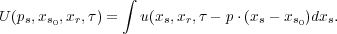
Figure 29 graphically describes how a plane wave source is generated from a set of shot profiles. Each source in the set is delayed (or advanced) in time by an amount determined by the desired plane wave moveout and its distance from the central source. The delayed shots are then summed to produced the desired plane wave response. This process is then repeated for each required plane wave.
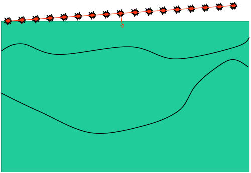
Plane wave sources produce a wavefield with a particular takeoff angle. Normally, takeoff angles are measured in degrees from level with zero representing a plane wave in the vertical direction. In the sense that only one plane wave can be generated with this take off angle, the resulting track is unique and the full plane wave is completely determined by this takeoff angle. Figure 30 conceptualizes the basic idea in ray theoretic terms. Here we see a plane wave with an apparent takeoff angle of approximately 30 degrees traveling, as indicated by the ray, through the subsurface media and striking a steeply dipping reflection event. The angle of the plane wave at this point also uniquely determines the raypath back to the source so either angle contains sufficient information to completely determine the raypath.
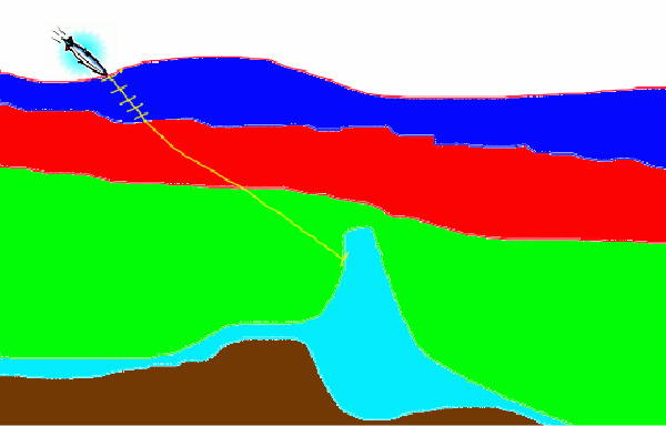
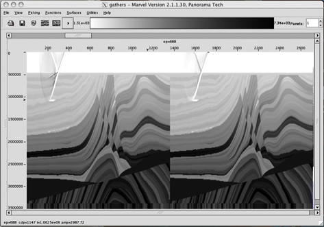
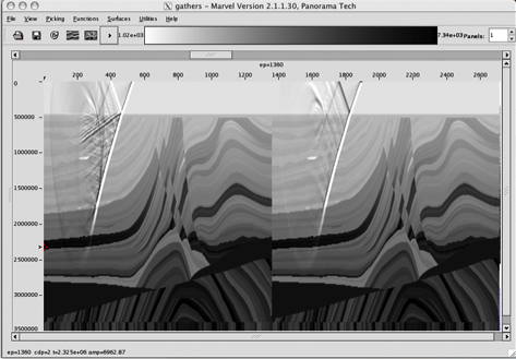
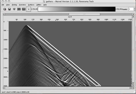
Figure 31 illustrates a plane wave propagating through the Marmousi2 model. Figure 32 is the actual response of the plane wave in Figure 31. While not something the typical geophysicist is familiar with this plane wave shot response can be migrated and imaged just like any traditional point source response.
- Introduction
- Seismic Modeling
- Primary Concerns
- Three Earth Models
- Seismic Acquisition: The Basic Idea
- Why Model?
- Waves and Wavefields
- The Scalar Wave Equations
- Stress-Strain Equations
- Algorithms
- Variational Formulation and Finite Elements
- Finite Differences
- Model Boundaries
- Fourier Based Methods
- A Word About Sources
- Huygens Principle and Integral Methods
- Raytracing
- Raytrace Modeling
- Zero Offset Modeling
- History
- Zero Offset Migration Algorithms
- Exploding Reflector Examples
- Prestack Migration
- Prestack Migration Examples
- Data Acquisition
- Migration Summary
- Isotropic Velocity Analysis
- Anisotropic Velocity Analysis
- Case Studies
- Course Summary
